Friday, November 4, 2022

 Intergrate Xshell 7 with EVE-NG

If you don't have Secure-CRT, use Xshell as an alternative to have multiple Telnet sessions in one window.

1. Download and install Xshell.

2. Copy the text below into a notepad,  update the Xshell version number accordingly - current version is 7and,  save the txt file as "Xshell.reg". 


[HKEY_CURRENT_USER\SOFTWARE\Classes\Xshell.telnet]

@="telnet"


[HKEY_CURRENT_USER\SOFTWARE\Classes\Xshell.telnet\DefaultIcon]

@="C:\\Program Files (x86)\\NetSarang\\Xshell 7\\Xshell.exe, 0"


[HKEY_CURRENT_USER\SOFTWARE\Classes\Xshell.telnet\shell]


[HKEY_CURRENT_USER\SOFTWARE\Classes\Xshell.telnet\shell\open]


[HKEY_CURRENT_USER\SOFTWARE\Classes\Xshell.telnet\shell\open\command]

@="\"C:\\Program Files (x86)\\NetSarang\\Xshell 7\\Xshell.exe\" %1"


[HKEY_CURRENT_USER\SOFTWARE\Xshell]


[HKEY_CURRENT_USER\SOFTWARE\Xshell\Capabilities]


[HKEY_CURRENT_USER\SOFTWARE\Xshell\Capabilities\URLAssociations]

"telnet"="Xshell.telnet"


[HKEY_CURRENT_USER\SOFTWARE\RegisteredApplications]

"Xshell"="Software\\Xshell\\Capabilities"


[HKEY_CURRENT_USER\SOFTWARE\Classes\telnet\shell]


[HKEY_CURRENT_USER\SOFTWARE\Classes\telnet\shell\open]


[HKEY_CURRENT_USER\SOFTWARE\Classes\telnet\shell\open\command]

@="\"C:\\Program Files (x86)\\NetSarang\\Xshell 7\\Xshell.exe\" %1"


3. Double click the Xshell.reg to update your Windows Registry. 

4. Reference this video to change the Windows Default App setting for Telnet to use Xshell.

5. You are almost done. If your Xshell session looks like this and you wish the session title to reflect device name:


Right click on the blue session title and select "Show Terminal Title".


Tuesday, August 10, 2021

How to upgrade Cisco IP Phone 7945G to SIP Firmware using Linux Box

Items you will be needing:


    - Linux Box with Ubuntu 

    - Cisco POE Switch

    - Cisco IP Phones

    - Ethernet cords


Download the files at https://software.cisco.com/download/home/281346594/type/282074289/release/9.3(1) and download 7945 and 7965 IP Firmware Files Only - Compatible CUCM Versions: 7.1(5)+


Install the DHCP Server by opening the Terminal and typing in sudo apt install isc-dhcp-server, then 

type in /etc/dhcp/dhcpd.conf in the terminal, press y, and paste in: 

option domain-name "example.org";

option domain-name-servers 8.8.8.8;

option tftpserver code 150 = array of ip-address;

default-lease-time 600;

max-lease-time 7200;

authoritative;

subnet 192.168.199.0 netmask 255.255.255.0 {

range 192.168.199.10 192.168.199.240;

option routers 192.168.199.254;

option subnet-mask 255.255.255.0;

option broadcast-address 192.168.199.255;

option tftpserver 192.168.199.2;

}


Then follow this guide online to install the TFTP server at https://help.ubuntu.com/community/TFTP


Here is a diagram of the Linux Box, POE switch, and the IP Phones.


Monday, August 2, 2021

How to upgrade Cisco IP Phone 7945G to SIP Firmware

                                    How to upgrade Cisco IP Phone 7945G to SIP Firmware

    Items you will need:
        - Cisco IP Phone 7945G
        - Cisco Switch with POE Ports
        - Any PC that can download software and change Firewall settings
        - At least 2 Ethernet Cords

    Preparations:
        PC:
            1. Download the IPSwitch TFTP Server at https://www.whatsupgold.com/free-network-monitoring-tools/free-tftp-server, then install it, open the program by pressing the Windows key, and typing in "IPSwitch TFTP Server".
            2. Press the Windows key, Type: "Windows Defender Firewall" and open it, Click Advanced Settings on the sidebar, then click Inbound Rules, and click new rule. Make sure the type of rule is on Program, and click next. Click "This Program Path" and fill in the path for where your IPSwitch TFTP Server program is. It should be in C:\Program Files (x86)\Ipswitch\TFTP Server. Make sure to click TFTPWindowsService.exe and not the program itself. Click next and click "Allow the connection", next again, and checkmark everything, then add a name to it. It doesn't matter what the name is, then click finish.
            3. Click the New Rule again to add a new rule, but this time for the rule type you need to click "Custom". Then press next twice, click the Protocol Type where it says "Any" and click ICMPv4. Again, click next until you need to give it a name, and again, it doesn't matter what the name is.
            4. Download the files at https://software.cisco.com/download/home/281346594/type/282074289/release/9.3(1) and download 7945 and 7965 IP Firmware Files Only - Compatible CUCM Versions: 7.1(5)+
    How to Upgrade the Phone Firmware
        1. Setup the DHCP Server on the switch.
            Connect your PC to the Console port and set up the DHCP Server.
            The configuration should be set to:
ip excluded-address 192.168.2.1 192.168.2.50
ip dhcp pool VOIP
network 192.168.2.0 255.255.255.0
default-router 192.168.2.1
dns-server 192.168.1.1
option 150 ip 192.168.2.51                       

        2. Connecting the Phone to the switch.
            Connect the Cisco IP Phone to the switch with an ethernet cable. It should cycle through a few different screens, but make sure it's upgrading. If it isn't, unplug the cable and plug it back in while holding the pound sign (#) until the two buttons on the right side of the screen blink a red color. Then press 123456789*0# which will soft reset the phone. It should then turn back on with the looping screen.

        3. Configuring the TFTP Server.
            Open the IPSwitch TFTP Server program, go to options, set your root folder to your directory where your firmware folder is, go to security and allow downloads and uploads, then click OK. Once the TFTP Server starts, the phone should start upgrading.

Tuesday, March 9, 2021


 Install VMware Workstation 16 Player and EVE-NG on CentOS 8

1. Follow this tutorial: https://linuxhint.com/install_vmware_player15_centos8/

2. Before download the VMware Player, install libnsl ("yum install libnsl"). This will help import the VOF file into the VM Player in later steps.

3. After download the VMware player, change file permission ("chmod a+x VMware-Player-16.1.0-17198959.x86_64.bundle")


Monday, December 14, 2020

Cisco Nexus ITD and Windows Server

Cisco Nexus switch offers ITD (Intelligent Traffic Director) services, which is like a load balancer. Here is a deployment guide: https://alln-extcloud-storage.cisco.com/ciscoblogs/ITD_DSR_Deployment_Guide_v5.pdf

Per Cisco, ITD won't support FEX. All the servers need to be directly connected to the Nexus switch directly.


In this example, I have a pair of Nexus 9K in VPC mode and two servers and a client. Here is a simple topology:


To make this work, there are two side of the configurations - Nexus side and Server side. 


On Nexus side:

Cisco has plenty of documents to outline the configuration tasks on Nexus side. See the deployment guide for details. Below is a sample of relevant configuration:

Nexus9396-Lab# sh running-config

......

feature pbr

feature interface-vlan

feature sla sender

feature sla responder

feature itd

......

vlan 201
  name Server_VLAN
vlan 202
  name iis
vlan 203
  name Workstation_VLAN
......

interface Vlan201
  description Server_VLAN_192.168.201.0/24
  no shutdown
  no ip redirects
  ip address 192.168.201.1/24

interface Vlan203
  description Workstation_VLAN_192.168.203.0/24
  no shutdown
  no ip redirects
  ip address 192.168.203.1/24

itd device-group servers
  probe icmp frequency 5
  node ip 192.168.201.10
  node ip 192.168.201.11


itd arr-lb
  device-group servers
  virtual ip 100.100.100.1 255.255.255.255 advertise enable device-group servers
  ingress interface Vlan201
  ingress interface Vlan203
  failaction node reassign
  load-balance buckets 2
  no shut


##########################################


On server side, 

1. Install a loopback interface on each server and assign the same virtual IP (e.g. 100.100.100.1/32) to this loopback interface o

2. Enable LAN routing on the server. Without this step, traffic will be lost after redirected from Nexus to the server via its primary IP.


Install loopback adapter on windows server 2019

1. Click on Start, and run hdwwiz,


2. click on Next


3. Select "Install the hardware that I manually select from a list (Advanced)


5. select Microsoft in the left, and Microsoft KM-TEST Loopack Adapter in the right, and go Next, Next, and Finish


Assign loopback interface the same virtual IP on both servers:


Enable Routing on both Servers:

1. From Server Manager, select Add Roles and Features


2. Select Remote Access and go Next, Next, Next


3. Select Routing and click Add Features. This will select DirectAccess ad VPN (RAS). Ignore it now and go Next and Install


4. After the installation, ope Routing and Remote Access console from Server Manager


5. Right click the server in the right pane and select "Configure and Enable Remoting and Remote Access"


6. Click Next in the Routing and Remote Access Server Setup Wizard


7. Select "Custom configuration" and go Next


8. Select "LAN routing" and go next and Finish


9. Click on "Start service"


Now you can ping the virtual IP you have defined in ITD service from the client machine. 


Other validation tasks you can do on Nexus switch is to run "show itd servers statistics" and disable one server, wait for 5 seconds, and run the show command one more time. You will see the traffic will be routed to the second server.

Monday, November 9, 2020

How to set up CheckPoint R80.40 Lab on EVE-NG from the Ground Up


I was a fan of GNS3. Lately, I found EVE-NG is more capable for large and dynamic labs. I will share how to set up EVE-NG on a ESXi server and how to set up a Check Point lab on EVE-NG. Nothing is new, just hope this could save you some time. 


Hardware, Software, and Topology


Hardware:

• Server: IBM x3690 X5 with 12-core Xeon E7 CPU, 144GB RAM, 2TB HDD

• Laptop: Dell Latitude

• Router: Asus Wireless router with 4 Gigabit ports


Software:

• ESXi 6.7

• EVE-NG Community edition 2.0.3-110 (https://www.EVE-ng.net/index.php/download/)

• EVE-NG Windows  Integration Pack ( - includes: Wireshark, UltraVNC, Putty, Plink, etc.)

• SuperPutty

• Cisco IOU i86bi-linux-l2-adventerprisek9-15.2d.bin (http://gns3.xyz/files/Downloads/Cisco-IOU-L2-L3-Collection-v4/bin/)

• Checkpoint R80.40 ISO

• Windows 2016 ISO

• CentOS ISO


Topology:


Start your configuration

First, set up your laptop:

1. Install EVE-NG Client Pack on your laptop

After installation, go to C:/Program Files/EVE-NG, rename “putty.exe” to “putty123.exe” 


2. Install SuperPutty (64-bit) on your laptop


After installation, copy the content of C:/Program Files(x86) /SuperPuTTY to C:/Program Files/EVE-NG, and rename “SuperPutty.exe” to “putty.exe”. This will make Superputty your default SSH client so that you can open multiple tabs in one SSH window.  


3. Install WinSCP on our laptop


Second, set up ESXi on your VM Host


This is straightforward and I used all the default settings. If you have any questions, please check out this video: https://youtu.be/WZQ6lVSkq4w

After the ESXi is installed, assign static IP for the host. In my case, I used 192.168.1.249, mask 255.255.255.0, gateway 192.168.1.1, DNS 192.168.1.1


Third, install EVE-NG on VM host


• Deploy a virtual machine (EVE-NG-Demo) using ovf. Detailed procedures can be found in this video: https://youtu.be/UYGoFyVqpYU

• I used following settings:


  • IP 192.168.1.200, mask 255.255.255.0, gateway 192.198.1.1; domain name: example.com; DNS: 192.168.1.1, 8.8.8.8; NTP:192.168.1.1; Proxy Server Configuration: direct connection;
  • The default hard drive for the virtual machine is 50 GB. You will need to add additional drive space (e.g. 200G) by shutting down the virtual machine and add another virtual hard drive.


Fourth, add nodes to the EVE-NG VM

Eve-NG is very sensitive to upper/lower case in file or folder name. If the How-to's uses all lower case or has a hyphen in file or folder name, please follow it exactly. 

Install Cisco IOL Image

o https://www.eve-ng.net/index.php/documentation/howtos/howto-add-cisco-iol-ios-on-linux/

and here is another reference link: https://youtu.be/OiPY3N1Tehk

o There might be a bug in the image and you will need to add “no ip cef” in the layer 3 switch configuration later.

Install Windows Image 

https://www.eve-ng.net/index.php/documentation/howtos/howto-create-own-windows-server-on-the-eve/

          EVE-NG is very sensitive to syntax and you need to have a hyphen in the folder name. 

Install Linux Image

o https://www.eve-ng.net/index.php/documentation/howtos/howto-create-own-linux-host-image/

o I had bad luck with the ready to use Linux image and used a fresh CentOS iso.

Install CheckPoint Image:

• Here are two links on how to set up CheckPoint image. Same procedure for R80.40 as previous version.

o https://www.eve-ng.net/index.php/documentation/howtos/howto-add-checkpoint/

o https://community.checkpoint.com/t5/General-Topics/Deploying-Check-Point-Solution-R80-40/td-p/94267


We are almost ready to set up the lab. Let’s double check the ESXi host’s virtual switch setting:


Just a reminder, 192.168.1.249 is the ESXi Host IP. EVE-NG virtual machine’s IP is 192.168.1.200.


Finally, setting up the lab

• On your laptop, from either Chrome or Firefox, go to https://192.168.1.200. The default username and password: admin & eve


• Add a new lab:


• Right click on the lab screen to bring up “Add a new object” menu and select Node:


• Checkpoint Security Gateway VE, Cisco IOL, Linux Host, and Windows host should be highlighted. Those are the images you have added in the previous setup. Select Checkpoint Security Gateway VE


• Create 4 Checkpoint nodes with 6 interfaces. One will be a management server, two will be the main site firewall gateway cluster, and the last one will be the branch office gateway.


• Repeat the same process to create two Windows servers with 2 interfaces and one Linux server with two interfaces:


• Add 4 Cisco IOL switches with 3 port groups:


• Finally, add a network object. This will be the access to the internet for all your lab nodes.


• You can right click on the node and modify the node name, Console access method, etc. See example below:


Here is a final topology for the lab.


What I have not included in the above topology is that from all the nodes, you can have a link to the INTER_Net node. This dual-homed connection is to allow all the nodes to directly connect to your WIFI router/Internet temporarily to download patches or applications. For example, the Linux web server will need the httpd package. Here is a KB (https://www.digitalocean.com/community/tutorials/how-to-install-the-apache-web-server-on-centos-7) on how to set up a website on the Linux server. 

By default, Check Point has 15-days evaluation license. To extend that, you will need to get eval licenses from Check Point for each node you are running: 

https://supportcenter.checkpoint.com/supportcenter/portal?eventSubmit_doGoviewsolutiondetails=&solutionid=sk102029

After you generated license file for each note, you can download them to your local machine. Then copy them to Win_MGMT server in your lab.

To apply the lab, you will need to copy the license files to each CP node. I used WinSCP on the Win_MGMT machine. I ran into an issue when I tried WinSCP and got a message saying the packet size is too large. To resolve that, please follow this link and change default shall for "admin" account:

https://supportcenter.checkpoint.com/supportcenter/portal?eventSubmit_doGoviewsolutiondetails=&solutionid=sk42178

After you WinSCP to the MGMT and GWs, transfer the "CPLicenseFile.lic" you got from Check Point to the default location and run following command on MGMT or GWs:

cplic put -l CPLicenseFile.lic


Saturday, April 20, 2019

Install Cisco csr1000v on ESXi

Based on Rob Riker's and Kevin Wallace's instructional video, I setup a virtual lab with a few Cisco csr1000v routers on an ESXi server. Those two video tutorials are awesome. You can click on the author's name to view the detailed steps.

The notes below is not step by step procedure. It just highlight a few important details that might save you some time.

  • Per Kevin's suggestion, use csr1000v-universalk9.03.11.02.S.154-1.S2-std.iso
  • You can use ESXi console to manage your router. But you can't cut & paste in the console session. To use Putty access to the virtual router, you will need Enterprise Plus license to use Virtual Serial feature on ESXi server.
  • By default, ESXi disables the Virtual Serial in its firewall policy and you will need to enable it. Even though it appears it only two ports are open for the virtual serial connection, it is not. Port 1024 and above are open.

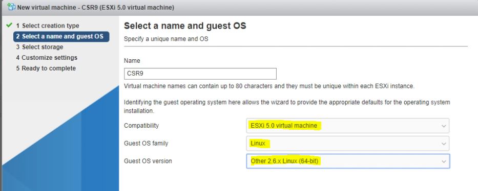
  • Instead of using ova template, I used the virtual router's ISO image to create virtual router/machine. Here are the VM settings and import settings are highlighted:


Note:192.168.4.187 is my ESXi server IP and
 CDROM is pointing to the router's ISO 
that uploaded to the Datastore earlier.

  • After you created the VM and power it on, it is important you get into the VM Console session immediately and hit any key to select "CSR 1000V Serial Console". If you miss the selection, you can restart right away the VM and try again. 


  • After the above selection, you can sit back and relax. Your VM will go through installation process and reboot again. If you see "Press any key to continue" again, ignore it.
  • After the router rebooted, it appears the router stopped at following message in the console session:
                                         Unable to open /dev/cdrom0
                                         INIT: Entering runlevel: 2
                                         INIT: Switching to runlevel: 3


  • You can get into the console session and hit keys, but goes nowhere. Don't worry, if you open a telnet session to the virtual router with the port you have defined in previous step (e.g. 192.168.4.187:2310), you will see your router is running normally :)
  • If you need to do more troubleshooting, you can get VM log from Datastore:


Wednesday, September 2, 2015

Error "Windows encountered a problem installing the driver software for your device. Windows found driver software for your device but encountered an error while attempting to install it" & "USB Receiver: No driver found".


Annoying problem with a new Logitech M185 wireless mouse - my windows 7 machine could not install the driver for the wireless adapter/receiver. Here is a solution I found online. I guess this can apply to other devices.


Re: USB unifying receiver won't install in W7/64bit


I have a Windows 7 Ultimate 64-bit workstation, and wanted to note that voltz solution about the usb.inf file worked for me. Here is what I actually did:

  • Browse to 'C:\Windows\System32\DriverStore\FileRepository\us​b.inf_amd64_neutral_e2b28ecac19a29af'
  • Copy usb.inf and usb.PNF to 'C:\Windows\INF\'
  • Update drive on unknown devices
  • -- In Device Manager, right-click and select Properties
  • -- Select Driver tab
  • -- Click 'Update Driver' button
  • -- Select 'Browse my computer for driver software'
  • -- Enter 'C:\Windows\INF\' in the Search for driver software in this location field and click Next
After that, the Unifying receiver was found and everything was great!

Wednesday, June 17, 2015

Use DBEDIT to Create Bulk Objects on Checkpoint Firewall

One of the repetitive tasks managing Checkpoint Firewall is to create blocked IP addresses and networks. It might be time consuming if you need to create a bulk of those via GUI. Based on a Checkpoint KB article, here is my weekly routine:

1. Log into your Checkpoint management server in expert mode and create a text file named "blockedaddress.csv" with two columns that separated by space. The first column is the IP address or network ID. The second column is the network mask. Here is an example:


              83.143.247.28 255.255.255.255
              223.223.176.0 255.255.240.0
               223.223.192.0 255.255.240.0
2. Create a script file named "blockCP.sh" in the same directory and Here is the content of the script:

#! /bin/bash
while read f1 f2
do
echo "create network block-addr-$f1" >>badip.txt
echo "modify network_objects block-addr-$f1 ipaddr $f1" >>badip.txt
echo "modify network_objects block-addr-$f1 netmask $f2" >>badip.txt
echo "update network_objects block-addr-$f1" >>badip.txt
echo "addelement network_objects Blocked-Networks '' network_objects:block-addr-$f1" >>badip.txt
echo "update network_objects Blocked-Networks>>badip.txt
done < blockedaddress.csv

This script will parse the csv file and generate a new text file called "badip.txt" that DBEDIT can use. The "block-addr-$f1" is the new network object based on the csv file. The "Blocked-Networks" is my existing object group and the new network objects will be added to. The "blockaddress.csv" is obviously the csv file we defined in step 1.

3. Run "sh block.sh" to generate the text file - "badip.txt".

create network block-addr-83.143.247.28
modify network_object block-addr-83.143.247.28 ipaddr 83.143.247.28
modify network_object block-addr-83.143.247.28 netmask 255.255.255.255
update network_objects block-addr-83.143.247.28
addelement network_objects Blocked-Networks '' network_objects: block-addr-83.143.247.28
update network_objects Blocked-Networks
create network block-addr-223.223.192.0
modify network_objects block-addr-223.223.192.0 ipaddr 223.223.192.0
modify network_objects block-addr-223.223.192.0 netmask 255.255.240.0
update network_objects block-addr-223.223.192.0
addelement network_objects Blocked-Networks '' network_objects: block-addr-223.223.192.0
update network_objects Blocked-Networks
create network block-addr-223.223.192.0
modify network_objects block-addr-223.223.192.0 ipaddr 223.223.192.0
modify network_objects block-addr-223.223.192.0 netmask 255.255.240.0
update network_objects block-addr-223.223.192.0
addelement network_objects Blocked-Networks '' network_objects: block-addr-223.223.192.0
update network_objects Blocked-Networks

4. Run "dbedit -local -f badip.txt"
5. Log into Dashboard, verify "Blocked-Networks" is updated and push policy.


Here are two reference doc:
https://supportcenter.checkpoint.com/supportcenter/portal?eventSubmit_doGoviewsolutiondetails=&solutionid=sk30383

https://supportcenter.checkpoint.com/supportcenter/portal?eventSubmit_doGoviewsolutiondetails=&solutionid=skI3301


If you have Cisco ASA, you can run this shell script against the same csv file to generate a text file to paste into ASA. Here is the sample script:

#! /bin/bash
echo "object-group network BlockNet_Group" >>badip4ASA.txt
while read f1 f2
do
 echo "network-object $f1 $f2" >>badip4ASA.txt

 done < blocklist.csv

The "BlockNet_Group" is the pre-existing object group in your ASA. You might need to remove the last line from "badip4ASA.txt.

Friday, April 10, 2015

Speed up TFTP transfer

We recently upgraded an ISR router at a remote site. The new code is very large and TFTP transfer took a long time. Pathping shows the the RRT is high and that might contributed to the slowness. After a little bit digging, it appears the TFTP program is using default block size of 512. This value can be increase to 8192:
R1(config)#ip tftp blocksize 8192
The TFTP program will also need to increase the block size accordingly.
Here is a comparison before and after the block size increase:

Destination filename [isr4400-universalk9.03.11.01.S.154-1.S1-std.SPA.bin]?
!!!!!!!!!!!!!!!!!!!!!!!!!!!!!!!!!!!!!!!!!!!!!!!!!!!!!!!!!!!!!!!!!!!!!!!!!!!!!!!!!!!!!!!!!!!!!!!!!!!!!!!!!!!!!!!!!!!!!!!!!!!!!!!!!!!!!!!!!!!!!!!!!!!!!!!!!!!!!!!!!!!!!!!!!!!!!!!!!!!!!!!!!!!!!!!!!!!!!!!!!!!!!!!!!!!!!!!!!!!!!!!!!!!!!!!!!!!!!!!!!!!!!!!!!!!!!!!!!!!!!!!!!!!!!!!!!!!!!!!!!!!!!!!!!!!!!!!!!!!!!!!!!!!!!!!!!!!!!!!!!!!!!!!!!!!!!!!!!!!!!!!!!!!!!!!!!!!!!!!!!!!!!!!!!!!!!!!!!!!!!!!!!!!!!!!!!!!!!!!!!!!!!!!!!!!!!!!!!!!!!!!!!!!!!!!!!!!!!!!!!!!!!!!!!!!!!!!!!!!!!!!!!!!!!!!!!!!!!!!!!!!!!!!!!!!!!!!!!!!!!!!!!!!!!!!!!!!!!!!!!!!!!!!!!!!!!!!!!!!!!!!!!!!!!!!!!!!!!!!!!!!!!!!!!!!!!!!!!!!!!!!!!!!!!!!!!!!!!!!!!!!!!!!!!!!!!!!!!!!!!!!!!!!!!!!!!!!!!!!!!!!!!!!!!!!!!!!!!!!!!!!!!!!!!!!!!!!!!!!!!!!!!!!!!!!!!!!!!!!!!!!!!!!!!!!!!!!!!!!!!!!!!!!!!!!!!!!!!!!!!!!!!!!!!!!!!!!!!!!!!!!!!!!!!!!!!!!!!!!!!!!!!!!!!!!!!!!!!!!!!!!!!!!!!!!!!!!!!!!!!!!!!!!!!!!!!!!!!!!!!!!!!!!!!!!!!!!!!!!!!!!!!!!!!!!!!!!!!!!!!!!!!!!!!!!!!!!!!!!!!!!!!!!!!!!!!!!!!!!!!!!!!!!!!!!!!!!!!!!!!!!!!!!!!!!!!!!!!!!!!!!!!!!!!!!!!!!!!!!!!!!!!!!!!!!!!!!!!!!!!!!!!!!!!!!!!!!!!!!!!!!!!!!!!!!!!!!!!!!!!!!!!!!!!!!!!!!!!!!!!!!!!!!!!!!!!!!!!!!!!!!!!!!!!!!!!!!!!!!!!!!!!!!!!!!!!!!!!!!!!!!!!!!!!!!!!!!!!!!!!!!!!!!!!!!!!!!!!!!!!!!!!!!!!!!!!!!!!!!!!!!!!!!!!!!!!!!!!!!!!!!!!!!!!!!!!!!!!!!!!!!!!!!!!!!!!!!!!!!!!!!!!!!!!!!!!!!!!!!!!!!!!!!!!!!!!!!!!!!!!!!!!!!!!!!!!!!!!!!!!!!!!!!!!!!!!!!!!!!!!!!!!!!!!!!!!!!!!!!!!!!!!!!!!!!!!!!!!!!!!!!!!!!!!!!!!!!!!!!!!!!!!!!!!!!
353459684 bytes copied in 7307.911 secs (48367 bytes/sec)


Destination filename [isr4400-universalk9.03.11.01.S.154-1.S1-std.SPA.bin]?
!!!!!!!!!!!!!!!!!!!!!!!!!!!!!!!!!!!!!!!!!!!!!!!!!!!!!.!!!!!!!.!.!!!!!!!!!!!!!!!!!!!!!!!!!!!!!!
353459684 bytes copied in 530.383 secs (666423 bytes/sec)


Monday, February 2, 2015

ASDM and Java

It seems I had bad luck using ASDM every time my company pushed out a Java update. I wish Cisco can do a better job to make it easy to use. Here are a few tricks I learned and hope to save you some time.


  • Read the ASDM release notes carefully.
  • Find a right version of Jave. Use 32-bit version.
  • http://blog.fpweb.net/how-to-run-dual-java-versions-for-compatibility/#.VM-sYWjF98E
  • Try to delete Java reference from C:\Users\XXXX\.asdm, C:\Users\XXX\AppData\Local or LocalLow or Roaming. XXXX is your login name on Windows machine
  • Edit Java Security setting from Control Panel, and add the ASA IP address in teh Exception Site list
  • Run ASDM from browser - https://x.x.x.x/admin/public/asdm.jnlp. You might need to configure your machine to run "jnlp" extension with Java Web Start (C:\Program File (x86)\Java\Jre7\bin\javaw.exe".
  • The worse case, use a VM with a version of working Java if you don't have control of your software upgrade policy.

Friday, January 2, 2015

VSS and vPC

There are several good documents and blogs about the VSS and vPC. Here are a few:

Here are sample configuration:

6500_S1 & 6500_S2


! CONFIGURE THE FIRST SWITCH: 65K1
!create virtual domain
65K1(config)#switch virtual domain 1
65K1(config-vs-domain))#switch 1
65K1(config-vs-domain))#switch 1 priority 110

!configure virtual switch link (VSL)
65K1(config)#interface port-channel 1
65K1(config-if)#switchport
65K1(config-if)#switch virtual link 1
65K1(config-if)#no shut

65K1(config-if)#interface range te1/1 – 2
65K1(config-if-range)#switchport
65K1(config-if-range)#switchport mode trunk
65K1(config-if-range)#switchport nonegotiate
65K1(config-if-range)#channel-group 1 mode on
65K1(config-if-range)#no shut
65K1(config-if-range)#end

!enable dual active detection – use fast-hello in this case
65K1(config)#interface te1/ 3
65K1(config-if)#no switchport
65K1(config-if)#no shut
65K1(config-if)#dual-active fast-hello

!turn on vss

65K1#switch convert mode virtual


! CONFIGURE THE FIRST SWITCH: 65K2
!create virtual domain
65K2(config)#switch virtual domain 1
65K2(config-vs-domain))#switch 1
65K2(config-vs-domain))#switch 1 priority 110

!configure virtual switch link (VSL)
65K2(config)#interface port-channel 2
65K2(config-if)#switchport
65K2(config-if)#switch virtual link 2
65K2(config-if)#no shut

65K2(config-if)#interface range te1/1 – 2
65K2(config-if-range)#switchport
65K2(config-if-range)#switchport mode trunk
65K2(config-if-range)#switchport nonegotiate
65K2(config-if-range)#channel-group 1 mode on
65K2(config-if-range)#no shut
65K2(config-if-range)#end

!enable dual active detection – use fast-hello in this case
65K2(config)#interface te1/ 3
65K2(config-if)#no switchport
65K2(config-if)#no shut
65K2(config-if)#dual-active fast-hello

!turn on vss
65K2#switch convert mode virtual


!verifying the VSS
65K1#show etherc sum
65K1#show switch virtual
65K1#show switch virtual role
65K1#show switch virtual link


N7K1 & N7K2

! CONFIGURE THE FIRST SWITCH: N7K1
!enable vpc feature and create vpc domain
N7K1(config)# feature vpc
N7K1(config)# vpc domain 1

! first, create a vrf
N7K1(config)#vrf context Keepalive

! create peer keep alive link (layer 3)
N7K1(config)#interface Ethernet 1/1
N7K1(config-if)#no switchport
N7K1(config-if)#ip address 10.1.1.11 255.255.255.0
N7K1(config-if)#vrf member Keepalive
N7K1(config-if)#no shut
N7K1(config-if)#vpc domain 1
N7K1(config-vpc-domain)# peer-keepalive destination 10.1.1.12 source 10.1.1.11 vrf Keepalive
N7K1(config-vpc-domain)#role priority 1

! configure vpc peer link
N7K1(config)#int Ethernet 1/ 2 – 3
N7K1(config-if-range)#switchport
N7K1(config-if-range)#switchport mode trunk
N7K1(config-if-range)#switch trunk allowed vlan all
N7K1(config-if-range)#switchport trunk native vlan 5
N7K1(config-if-range)#spanning-tree port type network
N7K1(config-if-range)#channel-group 1
N7K1(config-if-range)# interface port-channel 1
N7K1(config-if)# vpc peer-link

! config the vpc for a server with dual nic
N7K1(config)#int interface Ethernet 1/ 4
N7K1(config-if)# description SQL_Server1_Nic_1
N7K1(config-if)#switchport
N7K1(config-if)#switchport access vlan 5
N7K1(config-if)#spanning-tree port type edge
N7K1(config-if)#channel-group 51 mode active
N7K1(config-if)#no shut
N7K1(config-if)#interface port-channel 51
N7K1(config-if)#vpc 51


! CONFIGURE THE SECOND SWITCH: N7K2
! enable vpc feature and create vpc domain
N7K2(config)# feature vpc
N7K2(config)# vpc domain 1

! first, create a vrf
N7K2(config)#vrf context Keepalive

! create peer keep alive link (layer 3)
N7K2(config)#interface Ethernet 1/1
N7K2(config-if)#no switchport
N7K2(config-if)#ip address 10.1.1.12 255.255.255.0
N7K2(config-if)#vrf member Keepalive
N7K2(config-if)#no shut
N7K2(config-if)#vpc domain 1
N7K2(config-vpc-domain)# peer-keepalive destination 10.1.1.11 source 10.1.1.12 vrf Keepalive
N7K2(config-vpc-domain)#role priority 2

! configure vpc peer link
N7K2(config)#int Ethernet 1/ 2 – 3
N7K2(config-if-range)#switchport
N7K2(config-if-range)#switchport mode trunk
N7K2(config-if-range)#switch trunk allowed vlan all
N7K2(config-if-range)#switchport trunk native vlan 5
N7K2(config-if-range)#spanning-tree port type network
N7K2(config-if-range)#channel-group 1
N7K2(config-if-range)# interface port-channel 1
N7K2(config-if)# vpc peer-link

! config the vpc for a server with dual nic
N7K2(config)#int interface Ethernet 1/ 4
N7K2(config-if)# description SQL_Server1_Nic_2
N7K2(config-if)#switchport
N7K2(config-if)#switchport access vlan 5
N7K2(config-if)#spanning-tree port type edge
N7K2(config-if)#channel-group 51 mode active
N7K2(config-if)#no shut
N7K2(config-if)#interface port-channel 51
N7K2(config-if)#vpc 51

! verifying the vpcs
N7K1# show vpc brief
N7K1# show vpc consistency-parameters vpc 51
N7K1# show vpc consistency-parameters global